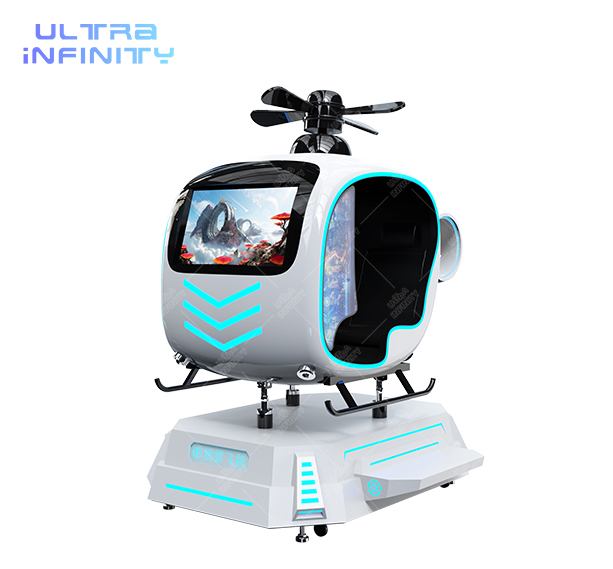
The body and the budget are two different numbers, and almost every published table prints only the first. A single-seat flight machine measures 1.46 m x 2.27 m of floor, stands 2.14 m tall, weighs 250 kg and draws 1 kW, which is 3.31 m2 of body, the VR simulator footprint a catalogue quotes. The floor you actually have to give it is 8 to 12 m2. That gap is not padding: it is clearance on every side plus the share of aisle the station needs once a briefing line, an operator console, a spectator row and an egress lane have each taken their own space. Plan by machine count and the zone is drawn two to three times too small before a single crate arrives.
Three numbers settle the question in the title. Budget 8 to 12 m2 per single-seat station and 12 to 17 m2 per dual-seat station, against bodies of 3.31 m2 and 6.36 m2. A 100 m2 flight zone holds 4 to 7 single-seat units, where we plan for 5, or 2 to 5 dual-seat units, where we plan for 3, so 4 to 7 seats or 4 to 10 seats from the same floor. Clear height is a ladder rather than one figure: 2.286 m is the IBC egress clearance floor, 3.2 m is what we recommend once a powered pod is running, 3.6 to 3.8 m covers 360 rotating units, and 4.5 to 6.0 m covers multi-seat flight cinemas. Everything below shows how those figures are produced so you can re-run them on your own floor plate.
Who this is for: a mall operator, an FEC owner or a leisure centre planner sizing a flight attraction before a lease or a fit-out quote is signed. What it gives you: a unit you can measure with a tape, a capacity formula that fits on one line, and a clear height ladder with the source of every rung named. What it is: a planning reference built from our own arithmetic on first-party machine specifications and on one published vendor clearance guide. It is not an industry standard, not a manufacturer layout guarantee, and not a replacement for the local fire and egress approval your drawing has to pass. Taken as a whole, the sections below are the flight simulator room requirements we work from, written as arithmetic rather than as a checklist.
Assumption. We plan one flight station cell at a clearance of 0.6 m per side, inside a published band of 0.5 to 0.8 m, and we apply an aisle factor of 0.85, inside a band of 0.80 to 0.90. The clearance band is reported by vartvrsimulator for its three-seat flying simulator, which specifies 500 to 800 mm of safety clearance on every side and a 1.2 m minimum walkway between stations. The aisle factor is our rounding of that walkway against the IBC minimum aisle width of 914 mm, so the factor carries a code floor and a vendor recommendation at the same time.
Formula. A_cell(c) = (L + 2c) x (W + 2c), where L and W are the machine body dimensions and c is the clearance per side. The aisle factor is applied one step later, when a zone area is converted into units, and it belongs to the next section rather than to this one. The cell formula itself is short enough to run on a phone while you are standing in an empty unit: add the clearance twice to each body dimension, then multiply.
Result. At c = 0.6 m the single-seat airplane needs 9.23 m2 of station cell, the two-seat helicopter 13.86 m2, and the one-seat 360 thunder fighter 10.27 m2. Move clearance to the tight end of the band, 0.5 m, and the same cells fall to 8.04, 12.41 and 9.00 m2. Move it to the loose end, 0.8 m, and they rise to 11.84, 17.00 and 13.04 m2. Those six pairs of numbers are our arithmetic on published body sizes, printed below so the calculation can be checked rather than trusted.
| Station | Body size (L x W) | Body area | Cell at c = 0.5 m | Cell at c = 0.6 m | Cell at c = 0.8 m |
|---|---|---|---|---|---|
| Single-seat airplane, 1 seat | 1.46 x 2.27 m | 3.31 m2 | 8.04 m2 | 9.23 m2 | 11.84 m2 |
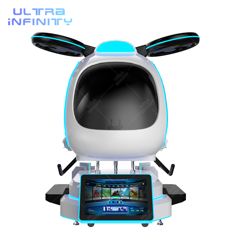
| Two-seat helicopter, 2 seats | 2.63 x 2.42 m | 6.36 m2 | 12.41 m2 | 13.86 m2 | 17.00 m2 |
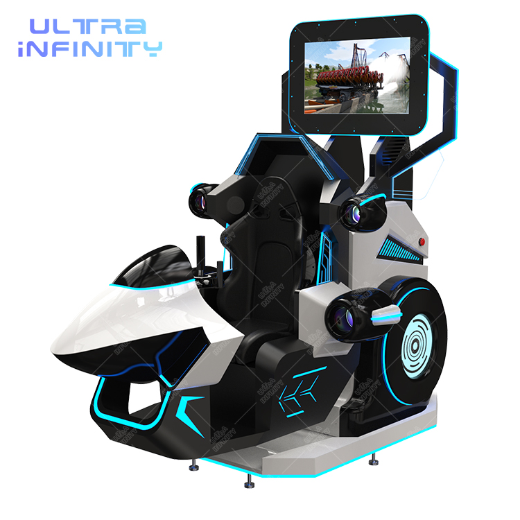
| 360 thunder fighter, 1 seat | 2.66 x 1.46 m | 3.88 m2 | 9.00 m2 | 10.27 m2 | 13.04 m2 |
The same arithmetic is what makes the smallest machine interesting rather than merely cheap. The single-seat 9D VR airplane machine is the tightest station in the range: 3.31 m2 of body, 1 kW of draw and 250 kg of mass, which turns into a 9.23 m2 cell and a body that clears a 2.5 m ceiling by 36 cm. That combination is why it is the model we reach for when a frontage is narrow or a slab is ordinary.
Limitation on the clearance band, because it decides how far you can push the tight numbers. The 0.5 to 0.8 m band is reported by one equipment maker for its own three-seat machine, so treat it as vendor-reported rather than as a code value. It has been adopted here as a planning band for fixed-position stations, and any drawing built on it still has to be checked against the product drawing and the local approval.
Rotating units are measured on a different basis entirely, and we keep that caliber in its own paragraph for that reason. Our published clearance for a 360 rotating chair is taken from the self-rotation arc and starts at 1.2 m, with a fenced envelope beyond it, as set out in our ceiling and power requirements for 360 VR chairs. The two measurements are never merged into one band here, because a merged number would be stated by neither source.
One more reference point, from the adjacent question that operators ask on the same visit. Chair-type machines and flight-type machines are sized the same way, and the chair question already has its own page: how much space a VR chair needs in an FEC covers the seat footprint version of this calculation, while this page covers the flying-station version with clearance, aisle and height attached.
The teaching point to take away before the next section: a table that counts machines is reporting an inventory, not a floor plan. A published FEC layout guide makes the same point when it warns that a 6.1 m2 cinema footprint should not be treated as a full operating area, and then stops short of saying what to add on top of it. The next section adds exactly that, for one specific floor area, with every assumption exposed.
The most common question we receive about VR flight simulator space is how many machines fit in 100 square metres, and planned the way we plan it, the answer is 4 to 7 single-seat units with 5 as the base case, or 2 to 5 dual-seat units with 3 as the base case. That is 4 to 7 seats or 4 to 10 seats from the same floor. Machine bodies account for only 15.5 to 19.1 m2 of the zone, roughly 16 to 19 percent of it; everything else is clearance, aisle, queue, briefing, operator storage, spectator room and egress.
Assumption, stated in full because the whole answer depends on it. Zone area is 100 m2, which is also the area anchor for the query most operators type. Fixed non-machine area is 40 m2, inside a band of 30 to 40, split as queue and briefing 12, operator console plus storage and charging 7, spectator seating 8, and entrance plus egress lanes 13. That split is our assumption and we label it as such: our own published 1000 m2 allocation model puts reception and queue at 7 percent and circulation and service at 12 percent across a whole venue, and a single flight zone cannot run at whole-venue ratios, so a higher share is taken deliberately. The four-zone structure of attraction, circulation, waiting and viewing, and the rule that the queue never crosses the motion zone, come from a published FEC layout guide; the 6 to 12 spectator seats per station come from the three-seat machine planning page.
Formula. Usable station area U = (A_zone - A_fixed) x aisle factor = (100 - 40) x 0.85 = 51 m2. Units N = floor(U / A_cell). Seats S = N x seats per unit. Run it per model and the base case falls out directly: 51 divided by 9.23 gives 5 single-seat airplanes, 51 divided by 13.86 gives 3 helicopters, and 51 divided by 10.27 gives 4 thunder fighters. The aisle factor is where the vendor 1.2 m walkway and the IBC 914 mm minimum aisle enter the calculation, so the 51 m2 is not the same thing as the 60 m2 of floor left after the fixed area is removed.
Result, as ranges rather than points, because a single number hides the clearance decision. Single-seat units: 4 to 7, base 5, tight case from 0.8 m clearance with the fixed area at 40, loose case from 0.5 m clearance with the fixed area at 30. Dual-seat units: 2 to 5, base 3. Thunder fighters: 3 to 7, base 4. Seats follow the units, so a dual-seat zone reaches 4 to 10 seats without adding a single station. Station cells total 34 to 63 m2 across the base and sensitivity cases, and the remaining floor is the fixed area plus the aisle margin.
| Model | Seats per unit | Station cell at 0.6 m | Base units in 100 m2 | Sensitivity band | Seats in base case |
|---|---|---|---|---|---|
| Single-seat airplane | 1 | 9.23 m2 | 5 units | 4 to 7 units | 4 to 7 seats |
| Two-seat helicopter | 2 | 13.86 m2 | 3 units | 2 to 5 units | 4 to 10 seats |
| 360 thunder fighter | 1 | 10.27 m2 | 4 units | 3 to 7 units | 3 to 7 seats |
Table 1 reads as one sentence: the same 51 m2 of usable station area buys five one-seat tickets or six seats worth of two-seat capacity, and the sensitivity band is the clearance decision plus the fixed-area decision rather than a margin of error we invented.
One warning about the phrase 100 sqm, because the same three words describe at least three different products and an automated answer will happily blend them. In the free-roam arena tier published by synthesisvr, 100 sqm is a 10 x 10 m open floor for walking players, one rung above 5 x 5, 6 x 6 and 8 x 8, and it holds a team of moving people rather than fixed stations. In the small-arcade comparison published by yhysimulator, 100 m2 is a whole-venue figure carrying 8 machines and 11 seats of mixed inventory with no clearance or clear height attached. In the start-up guide from vartarcade, 80 to 150 sqm carries 4 to 6 machines of mixed type, again at whole-venue scale. This page uses the fourth meaning: 100 m2 is a single flight work zone, clearance, aisle, queue and egress included.
That is also why the number we give differs from the number you will read elsewhere. A hundred square metres is genuinely enough for a compact flight zone, and it is not enough for eight flight machines, because eight stations of this class need 74 m2 of cells before the queue, the operator or the egress lane has taken anything. Any table promising eight units in 100 m2 is counting machines on a floor that has not yet been charged for the space around them.
The zone question and the capacity question belong to two different articles, and we keep them apart on purpose. How the attraction mix and the floor plan are drawn is covered in the flight and aerial combat zone guide for malls and family centers, which owns the layout side; this page owns the quantity side. Whether a small venue should be built from pods or from a large arena at all is the separate decision covered in simulator pods versus large VR arenas for small spaces, and the 100 sqm fork above is exactly where those two models stop sharing a vocabulary.
For the two-seat case the arithmetic is worth running once by hand, because it is the option that changes the seat count without changing the floor. The two-player VR helicopter simulator carries a 6.36 m2 body and a 13.86 m2 cell, so three cells take 41.6 m2 of the 51 m2 available and return 6 seats. Three single-seat airplanes take 27.7 m2 and return 3 seats. Same zone, same fixed area, double the tickets, and a 500 kg machine on the slab in place of a 250 kg one, which is the trade the next section of this page refuses to leave unexamined.
Limitation carried forward from the assumption layer: the 40 m2 fixed area is ours, not a published standard. If the zone shares a mall frontage or opens onto a main circulation spine, the fixed area can drop to 30 m2 and the single-seat count rises from 5 to 7, but the queue band is then borrowed from the shared space and the circulation has to be redrawn before that saving is real.
Flight simulator ceiling height is the one constraint that cannot be negotiated after the fit-out starts, so it is worth reading as a ladder with the source of every rung attached rather than as one recommended figure. The hard floor is 2.286 m, which is 7 ft 6 in of egress clearance under IBC, and it applies to the aisle rather than to the machine. Above that floor sit five practice rungs: 2.5 m of vendor activity clearance for a flight pod, 3.0 m as the motion-ride floor, 3.2 m recommended once a powered flight pod is running, 3.6 to 3.8 m for a 360 rotating unit, and 4.5 to 6.0 m for a multi-seat flight cinema.
Formula, so the ladder can be applied to a room rather than remembered. H_min = max(IBC egress clearance of 2.286 m, machine operating height plus clearance margin). The first term is a code floor that applies whoever supplies the equipment. The second term is model-specific: a 2.14 m single-seat body with a small margin clears at 2.5 m, a 2.82 m operating height asks for 3.2 m, and a rotating envelope asks for the 3.6 m minimum that our own 360 chair page publishes.
Table 2 below carries six rows because the first row is a code floor and the next five are practice rungs. Reading them as alternatives is the mistake the ladder exists to prevent: the code floor is not a design target, and the design target is not a licence to build below the code floor.
| Rung | Clear height | Whose caliber | What fits under it |
|---|---|---|---|
| 1. Egress clearance floor | 2.286 m (7 ft 6 in) | Building code: IBC means of egress, 2021 section 1017.2.2 and 2024 section 1030, subject to the locally adopted code | Aisles and circulation paths; any path with less than 80 in of clearance over it needs a barrier |
| 2. Flight pod activity clearance | 2.5 m | Vendor-reported flight space planning guide for entertainment venues | Our 2.14 m single-seat airplane, and single pods planned at 3 x 3 m or a multi-pod area of 30 m2 and above |
| 3. Motion ride floor | 3.0 m | Vendor site-readiness checklist for dynamic simulators | Motion cabins with limited vertical travel |
| 4. Powered flight pods | 3.2 m recommended, against a 2.82 m operating height | Vendor-recommended ceiling for a three-seat flying simulator | Our powered flight stations running at 2.82 m with margin above the cabin |
| 5. 360 rotating units | 3.6 m minimum, 3.8 m on the specification card | Our own published requirement for 360 VR chairs, with a 1.2 m self-rotation arc below it | Rotating flight chairs and rotating pods |
| 6. Multi-seat flight cinemas | 4.5 to 6.0 m | Vendor building height specs: 4.5 to 5.3 m for 6, 9 and 12 seat cinemas, 3.8 to 6.0 m for a 6 seat motion cinema | 6 to 12 seat flight cinemas and dome theatres |
The single most useful line in that table is the fourth one, because it decides which models a room can host at all. Below 3.2 m the only flight station we would place is the 2.14 m single-seat airplane, and even that machine sits under the constraint that the aisle above it still has to meet 2.286 m. Once a powered pod with a 2.82 m operating height is on the floor, a 3.0 m ceiling is not a comfortable fit, it is a moving machine running 20 cm from the structure.
Version discipline on the code row, since this is the number an inspector will read first. The clearance figure is quoted from IBC 2021 section 1017.2.2, which the 2024 edition carries at section 1030, and the local adopted code governs in every case. Say it that way on a drawing: per IBC, subject to the locally adopted code. A number quoted without its edition is a number that cannot be defended in a review meeting.
One caliber in that table is deliberately not usable for a commercial room. A consumer-oriented simulator room guide gives 8 ft minimum and 9 to 10 ft or more recommended for a home flight rig, with room widths of 10 to 15 ft. That is a residential direction, measured in feet, with no code clearance and no assembly occupant load attached, and it is recorded here only so nobody mistakes it for a venue figure.
The vendor rungs come from four separate published sources, and they disagree with each other in exactly the way the ladder is built to expose. A flight venue planning page puts user activity clearance at 2.5 m with 3 x 3 m single pods. A site-readiness checklist for dynamic rides puts the floor at 3.0 m. The three-seat flying simulator page runs a 2.82 m operating height and recommends 3.2 m above it. Our own 360 chair page asks for 3.6 m with 3.8 m on the card. None of the four is wrong; they are simply answering for different machines, and a room sized against one of them may be unusable for another.
Multi-seat cinemas widen the band further, which is why the top rung is a range. Published building heights for 6, 9 and 12 seat flight cinemas run 4.5 to 5.3 m, while a 6 seat motion cinema specifies 3.8 to 6.0 m of required height, and an 8 seat cinema lists 25 m2 of required space against that same tall envelope. If a projector dome or a large screen is involved the upper end of the band is the number to design to, not the midpoint.
Two pages carry the detail that this one only cites. The clearance and buffer wording for rotating units, including the 1.2 m arc and the 3.6 m minimum, is set out in what ceiling and power a 360 VR chair needs, and we quote it rather than restate it. The equipment list that a flight installation actually arrives with, and the height at which each item sits, is set out in the complete VR flight simulator equipment setup checklist, which is where to look once the room itself has passed.
Limitation on this whole section: heights are read at the lowest obstruction along the route, not at the slab. Ducts, cable trays, sprinkler heads and a suspended ceiling set the height you can use, and a clear height measured at the structural soffit is a number about the building rather than about the room you will operate.
Three constraints sit outside the area calculation and can still stop a layout: how much mass the slab takes, how wide the aisles have to be, and how people move through the room. The 40 m2 of fixed non-machine area in the capacity formula exists to pay for all three, and this section shows where each metre of it goes.
Floor load first, because it is the constraint that gets discovered late. Rotating and motion equipment in this class is published with a dynamic floor load requirement of 350 to 500 kg per square metre, and IBC designs an assembly occupancy for a 100 psf uniform live load with a concentrated load checked separately. Against those allowances sit our three machines at 250 kg, 500 kg and 380 kg. A single machine spread over its own footprint is rarely the problem; a loaded pallet crossing the slab, a leg loading one point, or two 500 kg machines in the same bay is what a structural drawing has to answer for.
Aisle width second, with two sources that point in the same direction. IBC sets a minimum aisle width of 36 in, which is 914 mm, calculated from occupant load and never allowed below that figure, under 2021 section 1017.2.2 and 2024 section 1030, with separate wider requirements for seating aisles in an assembly. The vendor planning guide for a three-seat flying simulator asks for 1.2 m between stations and a one-way circulation route. Where the two disagree we take the stricter value, which is how the 0.85 aisle factor in the capacity formula was set.
Circulation third, and this is where a drawing earns its keep. The published layout guidance for this category divides a zone into attraction, circulation, waiting and viewing, states that the queue must never cross the motion area, and asks for dimensions to be taken from product drawings rather than from photographs. A flight venue planning page splits the same floor into waiting and briefing, pods, spectator and maintenance. The three-seat simulator page adds a one-way route and 6 to 12 spectator seats beside the station. Those two rules, queue outside the motion envelope and spectators outside the queue, are what the fixed area is protecting.
| Fixed area component | Square metres | Basis for the figure |
|---|---|---|
| Queue and briefing | 12 | Our allocation assumption for a single flight zone; our whole-venue model runs reception and queue at 7 percent and circulation and service at 12 percent |
| Operator console, storage and charging | 7 | Operator station and back-of-house practice from the four-zone layout guidance |
| Spectator seating | 8 | 6 to 12 spectator seats beside each station, from the three-seat machine planning page |
| Entrance and egress lanes | 13 | IBC minimum aisle width of 914 mm applied to the entrance and the circulation lanes, plus the vendor 1.2 m station walkway where it is stricter |
| Total fixed non-machine area | 40 | Our assumption, band 30 to 40 m2 depending on whether the zone shares its frontage |
The table is the arithmetic behind the pie chart in the previous section, written out component by component so each line can be argued with separately. Taking 4 m2 out of the queue does not hand 4 m2 to the machines, because the aisle factor is applied after the subtraction; it adds 3.4 m2 of usable station area, and only after the circulation has been redrawn so the queue still does not cross the motion envelope.
The rotating model is the example we use for the load question, because it combines mass and motion in one footprint. The 360 VR thunder fighter weighs 380 kg, draws 2.5 kW and measures 2.66 x 1.46 x 2.33 m, and because it rotates it is also the model whose clearance has to be measured from the rotation arc rather than from the body. Two calibers, two sources, and a floor that has to satisfy the heavier of the two readings.
Power is named here only to keep the boundary visible. Our single-seat station draws 1 kW and the dual-seat and fighter stations draw 2.5 kW each, which is enough to plan a circuit per station and nothing more; how a whole building keeps its breakers closed during peak hours is answered in how much electrical power a 1,000 square metre venue needs, and we do not repeat that calculation here. The floor load figures above come from our 360 VR chair ceiling and power page, which is also the source of the 350 to 500 kg per square metre requirement.
Limitation, and it is the one that belongs to an authority rather than to a supplier. Occupant load, egress capacity and the aisle widths that follow from them are computed by the local approving authority against the adopted code. This page does not compute them, does not estimate how many people a room may hold, and does not substitute for the review. What it does is leave the floor area and the aisle width that such a review will need.
The three stations in this range are not ranked better or worse, they answer three different floors, and VR flight zone design starts from the room rather than from the catalogue. Start from the constraint you cannot change, which is almost always clear height or frontage, then decide whether you are selling seats or intensity, and only then look at a model. The decision points below are the ones that actually move a layout.
A fourth model appears in our catalogue without a published size, and the honest treatment of it is to say so rather than to estimate. The VR Thunder Fighter F2 is listed at 2 kW, 380 kg and one seat, with its dimensions still to be verified against the product page, so no area figure for it appears anywhere on this page. A station that cannot be measured cannot be placed in a cell, and an invented footprint would be worse than an omission.
One line of judgement before the models: intensity does not buy capacity. The fighter and the airplane take almost the same cell, 10.27 against 9.23 m2, so seats track stations one for one on either model. What the extra height and the rotation clearance buy is a different queue and a different ticket, not more machines on the floor.
Looking for a commercial VR flight simulator? The models below match the setups above. Send your floor plan and we will return a free 3D design with the cells drawn on it, and if you would rather see the motion logic first, how a VR flight simulator motion system simulates takeoff and flying explains what the machine is doing inside the envelope you are sizing.
Everything calculated on this page is our own arithmetic on published specifications and one vendor clearance guide, and the boundary of that arithmetic is worth writing out in full before anyone quotes a number from it as an industry figure. Six limits hold, and the first one governs the other five.
One practical consequence of the first limit: our arithmetic is fast enough to be wrong quickly. Run the cell formula, run the capacity formula, run the height ladder, and treat the output as a first layout to argue with rather than as a result to sign against. Where a number here disagrees with a product drawing, the drawing wins; where it disagrees with a local authority, the authority wins.
What the model is good for is the decision that comes before either of those: whether a floor plate can host a flight attraction at all, and which of the three stations it can host. That answer, with the cells drawn to scale, is what the layout request at the end of this page returns.
Pro Move: Stress-Test a Mixed Fleet Before You Sign the Lease. The formulas on this page are short enough to run in the letting agent office, and that is the point of what follows: before a lease is signed, run one mixed layout through the cell calculation, the fixed area and the height ladder, in that order. A VR arcade floor plan that has not been through those three runs is a wish list with dimensions attached. Mixed fleets fail before single-model fleets do, because the cell sizes stop being interchangeable and the usable area runs out while the machine count still looks acceptable.
Worked example, base case. Two single-seat airplanes, one two-seat helicopter and two thunder fighters: two cells at 9.23 m2, one at 13.86 m2 and two at 10.27 m2, which is 18.46 plus 13.86 plus 20.54 = 52.86 m2 of station cells. Usable station area in a 100 m2 zone at the base assumptions is 51 m2, so the mixed layout misses by 1.86 m2 and does not fit as drawn. Two ways out, both legitimate: take the fixed area down to 38 m2, which means borrowing 2 m2 from the queue or the spectator row, or raise the aisle factor to 0.90, which means the walkways are drawn at the tighter end of their band. Either fix has to be justified on the drawing rather than assumed.
Second run, sensitivity. Move clearance from 0.5 m to 0.8 m and the single-seat cell grows from 8.04 to 11.84 m2, which is the difference between a loose layout that reaches 7 units with the fixed area at 30 and a tight layout that stops at 4 units with the fixed area at 40. The band is wide on purpose: it is the honest width of a decision you have not made yet when you are still comparing units.
Third run, the height gate, which is checked last and decides fastest. H_min = max(2.286 m, operating height plus margin). A room at 2.9 m fails that gate for a powered pod at once, and no amount of floor area fixes it, so the answer is to change the model rather than the layout: the 2.14 m single-seat airplane is the way out, and it takes a 9.23 m2 cell in a room that other stations cannot enter.
The order is the whole method: cell, then fixed area, then ladder. A layout that fails at the cell step is a capacity problem, fixed by stations or clearance. A layout that fails at the fixed area step is a circulation problem, fixed by the queue, the spectator row or the entrance. A layout that fails at the ladder step is a building problem, fixed by changing the model or the unit. Change the input that failed; never change the formula to make a number fit.
Once the arithmetic survives all three steps, the drawing is worth looking at from the layout side, which is where the zone boundaries, the queue route and the spectator row get fixed: the flight and aerial combat zone guide for malls and family centers covers that half of the work. If the three steps pass, send the result to us at our free 3D layout service and we will return the cells drawn to scale with the fixed area split named on the drawing.
VR flight simulator space runs 8 to 12 m2 per single-seat station and 12 to 17 m2 per dual-seat station, which covers the machine body plus 0.5 to 0.8 m of clearance on every side and a share of the walkway. The bodies themselves are only 3.31 m2 and 6.36 m2, so a table that quotes the footprint alone understates the floor you need by a factor of two to three. Figures are our arithmetic on first-party specifications with a vendor-reported clearance band.
VR flight simulators 100 sqm is the shortest form of the question, and the answer is 4 to 7 single-seat units with 5 as the base case, or 2 to 5 dual-seat units with 3 as the base case, which is 4 to 7 seats or 4 to 10 seats. The calculation removes 40 m2 of queue, operator, spectator and entrance area from the 100 m2 zone, applies a 0.85 aisle factor to leave 51 m2 of usable station area, then divides by the station cell. Machine bodies account for only 16 to 19 percent of the zone.
2.286 m is the IBC egress clearance floor, 3.2 m is what we recommend for powered flight pods that run at a 2.82 m operating height, 3.6 to 3.8 m covers 360 rotating units, and 4.5 to 6.0 m covers multi-seat flight cinemas. Below 3.2 m only the 2.14 m single-seat airplane fits comfortably, and the locally adopted code governs the floor in every case.
350 to 500 kg per square metre for motion and rotating units, against an IBC assembly live load of 100 psf, with our three machines weighing 250 kg, 500 kg and 380 kg. For aisles, IBC sets a minimum width of 914 mm and the vendor planning guide asks for 1.2 m between stations, so plan to the stricter of the two readings.
No. A 10 x 10 m area is a published free-roam tier for walking players on an open floor, while a 100 m2 flight zone is workstation-based with clearance, queue and egress included, so it holds 4 to 7 single-seat units rather than a moving team. Whole-venue tables promising 8 machines and 11 seats in 100 m2 are counting mixed inventory with no clearance and no clear height attached.
Yes. We budget 40 m2 of a 100 m2 zone as queue and briefing 12, operator console with storage and charging 7, spectator seating 8, and entrance with egress lanes 13, and the queue never crosses the motion area. A zone sharing its frontage can work at 30 m2 of fixed area, but the circulation has to be redrawn before that saving is real.
Share your venue dimensions with our team and get a free 3D layout tailored to your space: station cells drawn to scale, the fixed area split named, the clear height rung your room actually meets. If the lease is not signed yet, send the floor plate and the lowest obstruction along the route, and we will tell you which of the three stations above fits before you commit to anything.